
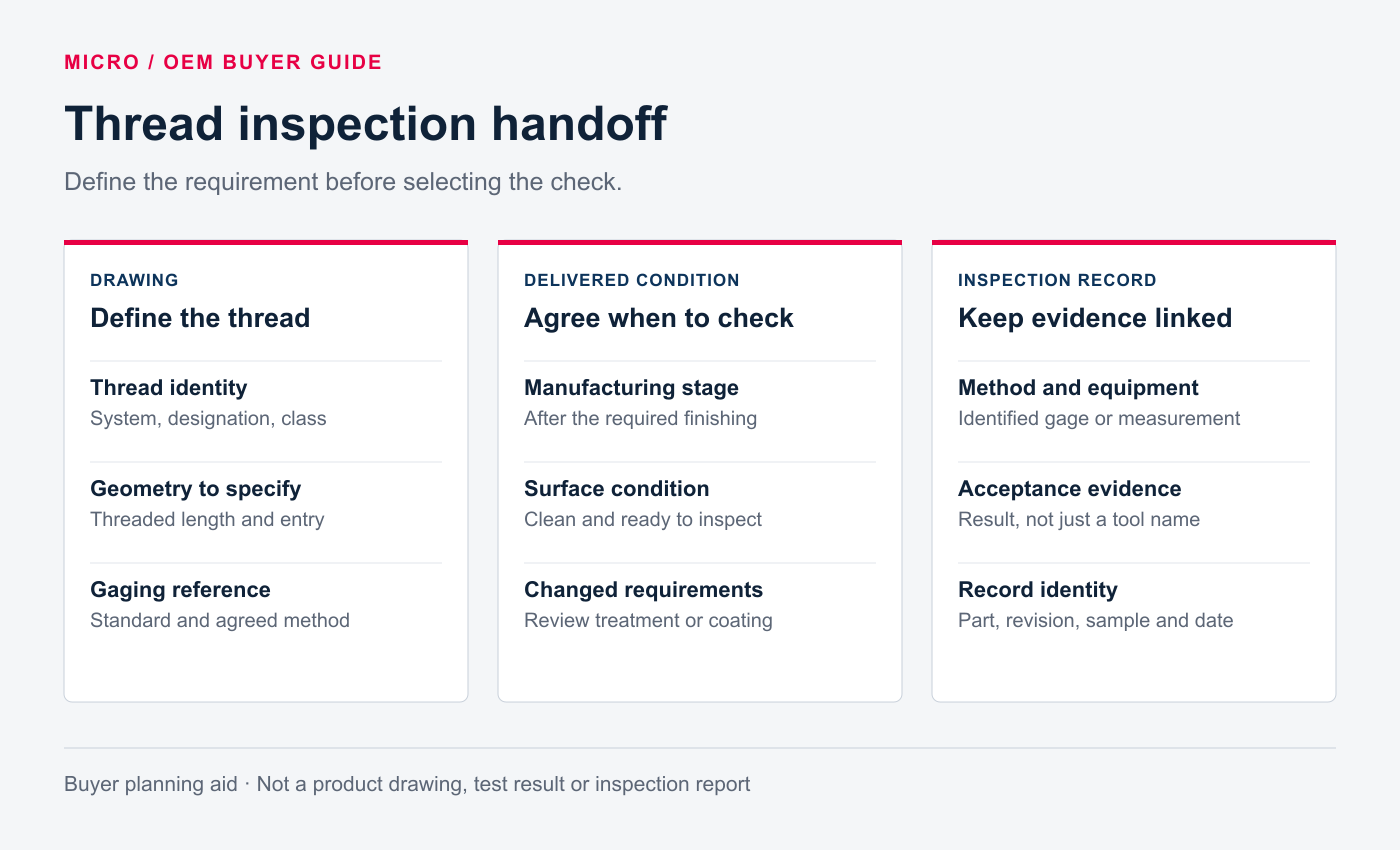
An inspection report that says “thread OK” can hide several different decisions. Was the specified thread system checked? Did the gauge reach the required usable length? Was the part inspected before coating or in its delivered condition? Before ordering custom CNC turned parts, turn those questions into an agreed inspection plan.
This guide concerns the purchasing handoff for a drawing-defined thread. It does not select a thread design, establish a universal gauging procedure or claim that every thread and gauge is available at MICRO.
Release a complete thread requirement
Identify the drawing revision, thread form or system, size, pitch or threads per inch, tolerance class and handedness where applicable. State the invoked standards and editions. A diameter without a thread designation does not tell a supplier which limits and gauge requirements to use.
Keep the thread requirement separate from nearby geometry. An external thread may also need a shoulder position or axis relationship controlled. An internal thread may need a location requirement relative to other features. Passing a thread gauge does not report all those separate drawing characteristics.
ISO 1502 addresses gauges for general-purpose ISO metric threads. ASME B1.3 describes acceptance systems connecting specified thread characteristics to the gauges used to inspect them. These scopes are not interchangeable instructions for every thread family. Confirm the system invoked by your actual drawing.
Decide what each inspection result must establish
Functional limit gauging and individual-element measurement answer related but different questions. A suitable thread limit gauge supports the acceptance decision assigned to it under the specified system. An individual pitch-diameter measurement supplies a measured characteristic; it does not automatically demonstrate the full functional requirement.
Likewise, checking an external major diameter with a micrometer is not a complete thread inspection. A report should identify which characteristics were evaluated and which were not. Ask for numerical results where the approval requires them, and identified GO/NO-GO outcomes where limit gauging is the agreed evidence.
A convenient production nut or screw is not automatically a substitute for a controlled inspection gauge. If a buyer requires a mating-part assembly check, define that as a separate test with an identified counterpart and acceptance criteria. Connect it with the sample approval process rather than treating an informal fit as universal proof.
Check access and usable thread length
For an internal thread, distinguish the specified usable thread length from the drilled-hole depth and the incomplete thread near a runout. A gauge reaching a physical stop does not, by itself, identify which of those lengths was checked.
Before quotation, show the entry direction, relevant depth references, counterbore or recess and any access obstruction. Ask the supplier how the method will reach and evaluate the required threaded region. OSG's gauge overview distinguishes plug gauges for internal threads, ring gauges for external threads and long-neck arrangements for difficult access. Its examples illustrate why gauge access must be reviewed; they do not prescribe equipment for every part.
Record effective thread-length verification separately where required. Do not resolve a missing depth definition by forcing a gauge farther or assuming that tool travel equals acceptable thread engagement.
Accept the delivered condition
State whether the thread must meet its acceptance requirements after coating, heat treatment or another operation. Intermediate checks can help control production, but their records should identify the stage they represent.
Do not apply a plain cylindrical coating allowance to thread geometry without the relevant specification and technical review. The coating and fit guide explains why coating thickness and finished dimensions need separate acceptance evidence. For a thread, agree the pre-process requirement, finished requirement and any masking or protected area on the drawing.
Include cleanliness and edge condition in the review. Debris or damage at the start can interfere with gauging, while cleaning or rework can change the condition being evaluated. Follow an agreed preparation and handling procedure, preserve rejected-condition evidence and obtain approval before rework. The burrs and edge-conditions guide helps identify which edges need explicit requirements.
Put seven decisions into the enquiry
The table is a planning checklist, not a MICRO inspection report or a qualified procedure. Complete it for the actual drawing before sample approval.
| Decision | Information to agree with the supplier |
|---|---|
| Thread definition | Drawing revision, system, designation, pitch, class and invoked edition. |
| Controlled region | Entry direction, usable length, depth reference, relief and access limits. |
| Acceptance scope | Functional limit gauging, individual measurements and separate geometry checks required. |
| Gauge identification | Gauge type, designation, identification and applicable condition or calibration status. |
| Finished condition | Operations completed before acceptance, including coating, preparation and handling. |
| Reporting and sampling | Characteristics, sample identities, quantities, results and agreed decision rule. |
| Disagreement or change | Hold, review and remeasurement process; approval before rework or specification change. |
Request the relevant gauge-use instructions for the invoked system. Do not copy a NO-GO engagement rule from a different thread family or apply a universal number of turns or torque from this article.
Gauge condition matters alongside correct identification. Define how wear or damage is detected and how the gauge's status is controlled. NIST's traceability guidance explains that traceability alone does not establish fitness for the measurement task. Calibration supports the method; it does not guarantee every decision made using that gauge.
Resolve a disagreement before releasing parts
If supplier and incoming results differ, preserve both reports. Compare the same identified part, drawing revision, thread designation, gauge identities, inspection stage, preparation, engaged region and operating method. A supplier's “GO passes” and a buyer's numerical result may not even describe the same acceptance characteristic.
Close the information gaps and agree remeasurement under the applicable procedure. Record the outcome and the basis for any disposition. Do not select the preferred report, change limits retrospectively or treat rework as approved merely because a gauge subsequently fits.
For a MICRO enquiry, send the thread definition, drawing, quantities, finished-condition requirements and requested evidence together. Our quality page describes existing inspection resources; the actual thread-manufacturing and gauging scope must be confirmed for the component. Use the RFQ checklist to keep technical and commercial requirements together.
Start an enquiry and email the drawing and thread-inspection requirements to [email protected] with the enquiry reference. Agree the acceptance plan before production.