

An outside chamfer can look clean while an unwanted projection remains where a cross-hole enters an internal bore. Removing more material is not automatically the answer: it can also change the shoulder contact or groove geometry the assembly needs.
For buyers of custom CNC turned parts, the useful specification identifies which edge matters, what condition is acceptable and what evidence will demonstrate it. This guide uses three edge locations to turn a general deburring note into an agreement that manufacturing and incoming inspection can both use.
Separate burr removal from the required edge shape
A burr is an unwanted projection left at an edge by machining. A deliberately specified chamfer or radius is part of the intended geometry. Removing the projection does not necessarily create the required chamfer; producing a chamfer does not establish the condition of every other edge.
There is also a third requirement: how much change is permitted around an edge that does not need a particular geometric shape. Excessive material removal can affect an adjacent locating face or narrow feature even when the edge feels smooth.
ISO 13715:2017's public overview addresses the indication and dimensioning of edges of undefined shape. It distinguishes that scope from explicitly defined edge geometry. Use the drawing's governing specification for the actual indication and limits; this guide does not prescribe standard symbols or default edge allowances.
“Deburr all edges” therefore leaves important decisions open. It does not identify protected surfaces, permitted removal, acceptance conditions or inaccessible areas. A useful note combines the intended outcome with those boundaries.
Identify E1, E2 and E3 on the drawing
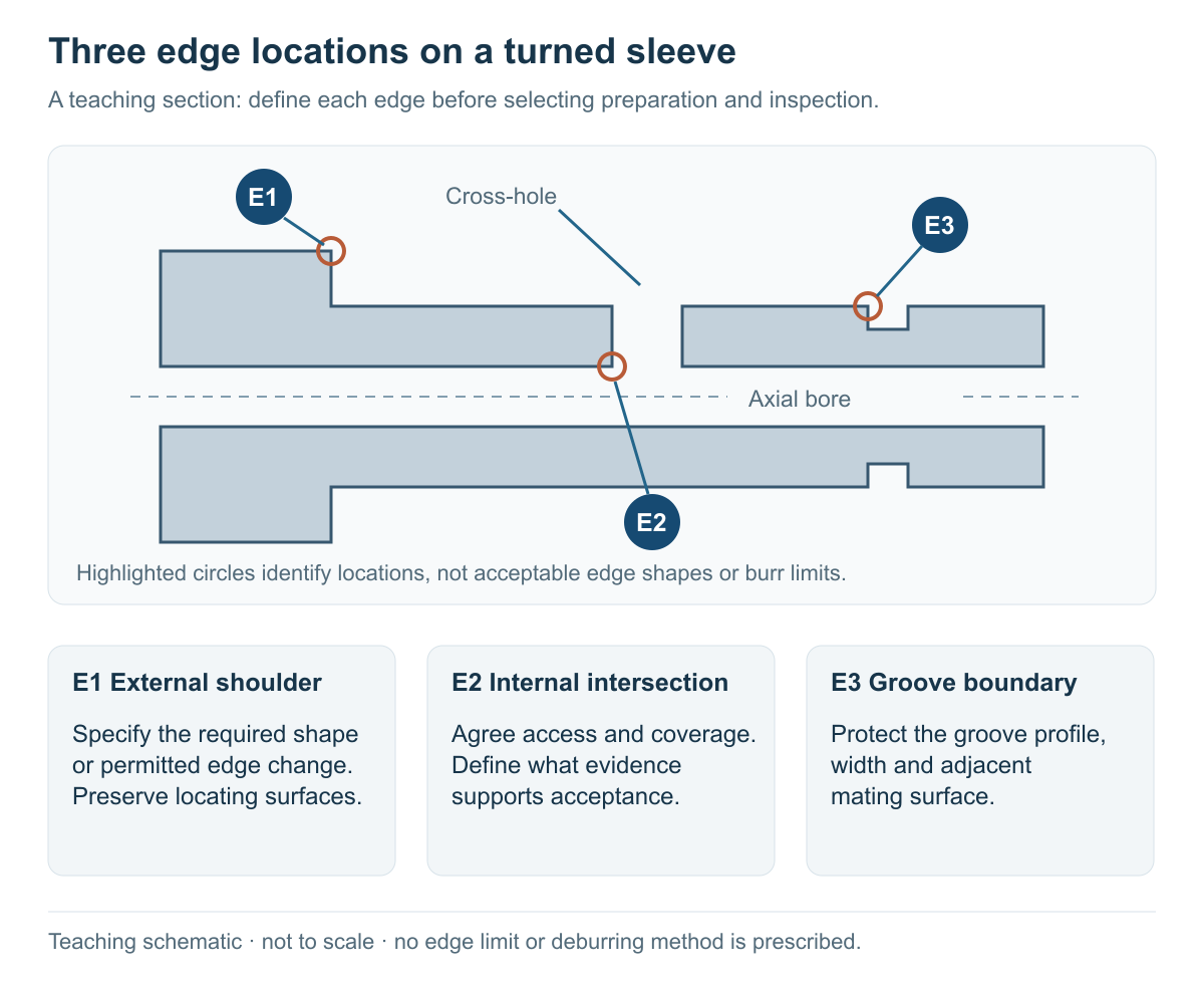
E1, E2 and E3 are teaching references, not MICRO part numbers or a customer inspection record. The schematic is not to scale.
E1: external shoulder or chamfer. Identify whether the design needs a defined chamfer, a radius or an edge condition without a particular shape. Protect the face that locates the mating component and the adjoining diameter. An unspecified blend around a shoulder is not an approved substitute for its drawing geometry.
E2: cross-hole/internal-bore intersection. The external hole entrance and the internal intersection are different locations. Define the internal edge separately, including its extent around the intersection. A photograph looking only at the outside entrance cannot establish the concealed condition.
E3: circumferential groove boundary. State the groove profile and which lip or lips need edge control. Preserve the required width, root geometry and adjacent functional surface. A general rounding operation should not silently change those requirements. The shaft drawing guide explains how feature references and geometric controls remain part of the complete specification.
Record an edge-specific acceptance agreement
The table is a teaching example of the agreement's structure. Replace its references with released drawing requirements and approved limits before accepting production.
| Edge | Required outcome | Geometry to protect | Inspection coverage and stage |
|---|---|---|---|
| E1: shoulder edge | Produce the drawing-defined edge; evaluate residual projections against the agreed criterion | Locating face and adjoining mating diameter | Identify the controlled circumference, viewing/measurement conditions and delivered-part stage |
| E2: internal crossing | Evaluate the actual internal intersection against the specified edge condition | Bore and cross-hole geometry outside permitted edge modification | Agree access to the defined intersection, evaluated extent, sample coverage and final-condition evidence |
| E3: groove lip | Meet the edge requirement while retaining the specified groove profile | Groove width, root/profile and neighbouring surface | Inspect the relevant lips and recheck affected groove characteristics after any rework |
For every row, record whether evidence covers every supplied part or an agreed sample, and which record identifies that coverage. A dimensional report and an edge observation may be separate evidence; neither should silently stand in for the other.
An approved visual reference can help describe appearance when its viewing conditions and scope are clear. It cannot replace a numerical requirement where one is specified. Keep surface texture separate too: an Ra result is not an edge-condition result. See surface roughness versus dimensional tolerance.
Resolve access before selecting or approving the route
Sandvik Coromant's cross-hole drilling guidance identifies chip evacuation and deburring at the crossing as particular challenges. HEULE's cross-hole guidance discusses different intersection geometries and restricted access.
For the buyer, the implication is specific: the route and inspection plan must reach the location named E2, not merely the visible entrance. These manufacturers' tool descriptions are background, not evidence that MICRO uses their systems.
Where direct observation is restricted, agree a suitable evaluation approach during qualification. Record any area not evaluated. If a sectioned trial sample is proposed, authorize that separately and define what its result can establish. Do not describe an unseen area as accepted merely because accessible edges look satisfactory.
Keep edge preparation visible in the process proposal. The turning process-selection guide covers the wider support and access review; a machine category alone does not establish edge acceptance.
Three disposition examples with different outcomes
E1 meets the appearance reference, but its chamfer exceeds the drawing. The appearance observation does not cancel the dimensional issue. Identify affected parts, record the deviation and obtain an authorized disposition. Additional polishing is not a remedy for already excessive material removal.
E2 was not visible under the agreed inspection setup. This is an evidence gap, not a passing result. Complete the agreed evaluation or approve a revised method before releasing the affected scope. If geometry prevents the required access, resolve the route or design requirement rather than replacing internal inspection with an external photograph.
An E3 projection can be removed, but the proposed rework may change groove width. Review the permitted modification first. After authorized rework, evaluate both the edge and affected groove characteristics. A smooth lip alone does not demonstrate that the groove still meets its drawing.
These are hypothetical decision examples, not reported MICRO defects or test results. They show why conformity, missing evidence and proposed rework need different decisions.
Confirm the delivered condition and reporting scope
If subsequent grinding, treatment or another operation changes the state being delivered, specify when edge acceptance must be demonstrated and whether earlier checks require confirmation. A pre-treatment observation does not document the later condition.
MICRO's manufacturing information identifies CNC and Citizen/Tsugami Swiss-type turning, centreless grinding and treatments arranged to specification. The edge-preparation method and inspection arrangement for a particular drawing are confirmed during review.
Its quality approach includes camera sorting of defined appearance and dimension items. That scope does not automatically establish coverage of a concealed cross-hole intersection. List critical internal edges and required evidence explicitly.
Add the edge agreement to the RFQ package, with the material, finished condition and quantities. At the sample approval stage, review the identified edges and records before releasing the agreed production scope. To discuss a component, start an enquiry and email the drawing to [email protected] with the inquiry reference.