
Grooved Shafts
Custom shafts with circumferential grooves, made to customer drawings. Define the groove geometry and its position alongside the shaft diameters, ends and mating requirements for quotation.
- Groove geometry to drawing
- Axial positions referenced to your datum
- Edges and adjacent surfaces reviewed together
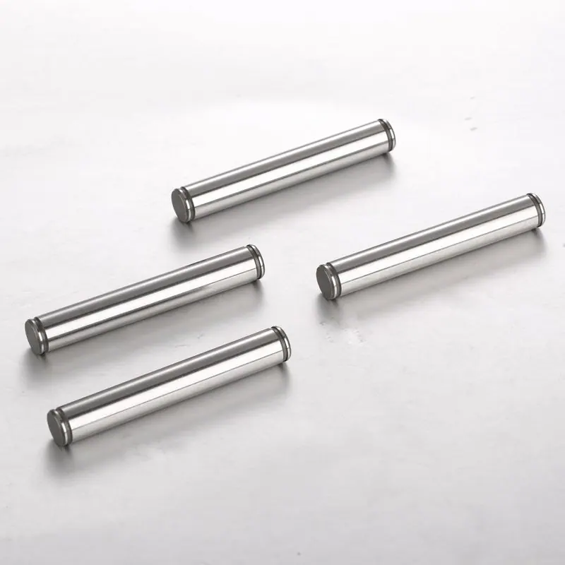
A groove is part of the complete shaft
The photograph shows cylindrical shafts with visible grooves near their ends. These are custom manufacturing examples. The image provides a view of the form, while your drawing defines the dimensions and function. We review each groove together with the surrounding shaft features, rather than treating a similar appearance as evidence that two parts have the same specification.
Locate grooves from a clear reference
Show groove width, depth or root diameter, and the position along the shaft. State which face or other feature provides the reference. Where more than one groove is present, dimension their relationship clearly. Include any edge or surface requirement and explain the mating component when it affects the required geometry. A photograph alone cannot communicate these details.
Specify the surfaces around the groove
Adjacent diameters, end chamfers and changes in section also belong in the quotation drawing. Tell us the material grade and condition and any treatment requirement, including which surfaces it concerns. Turning and grinding are available within our shaft manufacturing work; the suitable sequence and inspection plan depend on the complete part. Final tolerances follow the reviewed drawing, with no default value inferred from the image.
Prepare a groove-specific enquiry
Include a drawing revision, order quantity and required date. Mark the grooves or mating areas that need particular inspection records. The shaft drawing checklist covers drawing preparation, and our RFQ checklist lists quotation inputs. See the precision shaft family for related examples, then send your enquiry.
Key facts
- Groove cross-section
- Width, depth or root diameter and profile to drawing
- Axial location
- Position from the stated datum and between grooves
- Neighbouring features
- Adjacent diameters, shoulders, chamfers and ends
- Edge requirements
- Specify groove edges and any surface requirements
- Mating information
- Identify the mating component where relevant to review
The table lists information to supply for your part. No photographed shaft has an assigned public size, material grade or fit class.
Questions
Does a visible groove identify a retaining-ring size?
No ring specification is established by the photograph. If a ring is part of your assembly, supply its requirement and the corresponding groove dimensions on the drawing.
Can I use a photograph instead of groove dimensions?
A photograph can help explain the form. For quotation and manufacture, provide a drawing or sample for evaluation and identify the geometry that still needs confirmation.
Send your drawing for review
Start an inquirySubmit the inquiry form
Part, quantity, application and requirements. You receive an inquiry reference straight away.
Email your drawing
Send drawings or files to [email protected] and quote the reference.
Engineering review and quote
We check manufacturability and reply with questions or a quotation.