
A coating can satisfy its thickness requirement and still close a mating clearance. For buyers of precision pins and bushings, the drawing must connect the treatment, its permitted build-up and the dimensions required in the delivered condition.
The practical decision is whether the whole finished-size band meets the assembly requirement. A nominal layer thickness alone cannot settle that question.
Define what the coating allowance represents
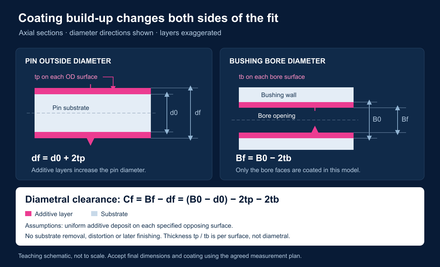
Here, coating thickness means the layer thickness measured normal to the substrate surface. Here, coating compensation means the provision made for coating-related size change so that the finished mating features meet the specified fit. It is separate from a formal fit-allowance definition in an engineering standard. A radial layer thickness and a diametral size change are different quantities.
Use these symbols for the simplified model:
- d0: pin diameter before coating; B0: bore diameter before coating.
- tp: uniform additive thickness on each opposing pin surface.
- tb: uniform additive thickness on each opposing bore surface.
- C: diametral clearance, calculated as bore diameter minus pin diameter.
Then d finished = d0 + 2tp, B finished = B0 − 2tb, and C finished = (B0 − d0) − 2tp − 2tb.
These equations assume cylindrical features, uniform additive deposit on the specified opposing surfaces, and no substrate removal, distortion or subsequent material removal. They describe size arithmetic, not an installed-fit guarantee. The mating-fit guide covers the wider interface review.
Work through the complete tolerance band
This hypothetical example uses millimetres. Its values are teaching inputs, not recommended coating thicknesses, MICRO capabilities or a customer result. Both the pin OD and bore ID receive the assumed uniform deposit.
| Quantity | Assumed limits, mm | Midpoint, mm |
|---|---|---|
| Pre-coating pin d0 | 5.980–5.986 | 5.983 |
| Pre-coating bore B0 | 6.030–6.040 | 6.035 |
| Pin thickness tp | 0.004–0.006 | 0.005 |
| Bore thickness tb | 0.003–0.005 | 0.004 |
At the midpoints, the finished pin is 5.983 + 2 × 0.005 = 5.993 mm. The finished bore is 6.035 − 2 × 0.004 = 6.027 mm. Clearance is therefore 0.034 mm, or 34 µm. The original midpoint clearance was 52 µm; the two deposits consume 18 µm.
For minimum clearance, combine the smallest bore, largest pin and greatest permitted deposit:
Cmin = B0,min − d0,max − 2tp,max − 2tb,max
= 6.030 − 5.986 − 2 × 0.006 − 2 × 0.005 = 0.022 mm.
For maximum clearance, use the opposite limits:
Cmax = B0,max − d0,min − 2tp,min − 2tb,min
= 6.040 − 5.980 − 2 × 0.004 − 2 × 0.003 = 0.046 mm.
The predicted band is 22–46 µm, assuming all combinations are permitted. The buyer must compare that entire band with the assembly requirement. A passing 34 µm midpoint alone cannot establish suitability. If the band is unsuitable, review the size limits, thickness limits, coating coverage or approved process sequence before ordering.
This worst-case stack is not a prediction of how frequently the limits occur. It also leaves roundness, alignment and installed bushing deformation outside the calculation. Keep those functional requirements in the drawing and assembly review rather than treating positive arithmetic clearance as proof of free movement.
Do not apply 2t to every surface treatment
The equations use additive build-up, not treatment depth in general. Anodizing converts part of the substrate into oxide; Anoplate's hardcoat explanation distinguishes penetration from outward growth. Its process example is not a universal compensation ratio.
A diffusion depth, conversion-layer thickness or material-removing treatment likewise does not automatically equal outward growth. Ask what dimensional change the specified process produces, including preparation and later operations. Confirm the actual treatment during drawing review rather than substituting an assumed plating allowance.
Specify local thickness and masking boundaries
An average thickness does not establish the build-up at every mating location. Technical Plating distinguishes average, minimum and maximum requirements; its uniformity guidance explains why recessed and shielded areas can plate differently from exposed surfaces.
Identify the functional length of the pin OD and bore, local minimum and maximum thickness, and evaluation locations. For internal geometry, resolve access and coverage along the bore; an entrance reading cannot establish the full length.
Where masking is required, mark the protected surfaces and boundary position, including the permitted transition region. A masking note needs an agreed outcome at the boundary. If later grinding or other finishing is proposed, confirm how it affects both final size and retained coating before approving the route.
Accept coating and finished geometry separately
Measure the delivered pin and bore against the final dimensional requirements. Evaluate coating thickness at the specified locations with an agreed method, coverage and acceptance rule. Keep surface texture separate: roughness and dimensional tolerance describe different requirements.
Fischer's XRF guidance identifies layer composition, positioning, cylindrical geometry and shading among relevant measurement factors. ASTM B487's public overview describes local coating-thickness measurement by microscopic cross-section examination. Neither reference selects the method for this component; confirm suitability and any destructive-sample authorization.
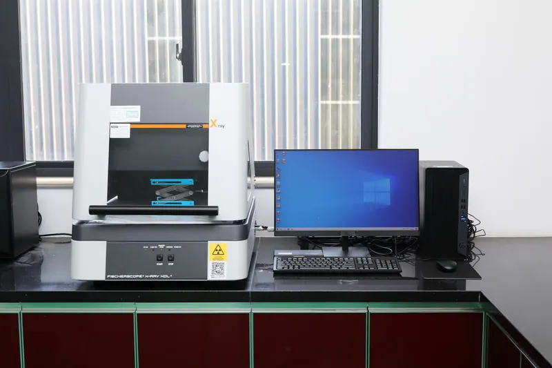
MICRO's quality page lists a Fischerscope X-RAY XDL 210 in its laboratory. Equipment presence does not guarantee access, method suitability or a measurement result for a particular bore or coating system.
Put the finished condition into the RFQ
Include the drawing revision, substrate material, treatment specification, coated and masked surfaces, thickness limits, final size limits, quantities and required records in the RFQ package. State whether each dimension applies before or after treatment and identify unresolved requirements.
MICRO's manufacturing information identifies CNC and Swiss-type turning, centreless grinding, and treatments arranged to drawing and specification. The route for a particular coating requirement needs confirmation. Start an enquiry, then email the drawing to [email protected] with your inquiry reference. The form also accepts an HTTPS drawing link; it does not accept file uploads.