
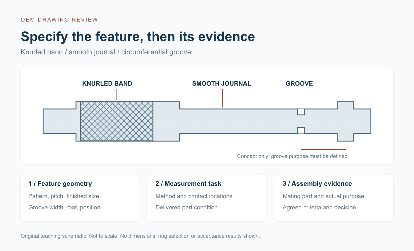
A drawing that says only “knurl here” or “groove for clip” leaves important assembly decisions unresolved. The part may resemble a photograph while the mating hub, retaining ring or inspection method remains undefined. Before requesting a quotation, connect each feature to the job it performs and the evidence needed to accept it.
This guide applies to purchasing custom precision shafts and CNC turned components. It is a specification checklist, not a promise that a particular tool, retaining system or assembly test is included in a MICRO quotation.
Begin with the assembly function
A textured band may be intended for handling, engagement with a mating component or another defined purpose. A circumferential groove may locate a retaining ring, provide clearance or serve a different function. Tell the supplier which applies. Similar-looking features can need different dimensions, edge conditions and verification.
Identify the mating part, assembly direction, contact region and required operating behavior. If a hub must resist movement, define how the complete assembly will be evaluated. A textured appearance alone does not establish holding force. Likewise, seeing a ring seated in a groove does not establish the load capacity of the retaining arrangement.
Specify the knurl beyond its appearance
State the pattern and the governing designation or drawing detail, including the relevant pitch and geometry. Accu-Trak's technical reference distinguishes circular and diametral pitch, and normal and transverse measurements. Clarify the convention being referenced; a description such as “medium” is not a complete pitch specification.
The Hommel+Keller knurling reference distinguishes knurl forming from knurl cutting. Forming displaces material; cutting removes material. Discuss which route is proposed when it affects the finished feature, surrounding geometry or agreed assembly behavior. This guide does not select a process from a photograph.
Define the axial extent of the textured band and its location relative to an identified shoulder, end or datum. State the finished diameter requirement over the knurl and how that diameter will be evaluated. The smooth blank diameter before forming is a manufacturing input; it should not silently replace the specified finished feature.
Also resolve whether incomplete pattern near the band ends is permitted and how adjacent bearing, sealing or locating surfaces will be protected from damage. Any acceptance limit needs its own requirement; a reference image can explain intent but does not supply missing numerical criteria.
Match a retaining groove to the selected system
Start with the intended ring or retaining element and its supplier drawing. Review its recommended groove geometry for the actual shaft arrangement. Width, root diameter, axial position and corner details can each affect installation or engagement. Avoid combining a familiar ring name with a groove copied from a different system.
Use the retaining-system manufacturer's application information to review loading and assembly conditions. Smalley's ring-design guidance treats ring shear and groove deformation separately and identifies limitations for dynamic loading. Review the selected system and its actual conditions; a component drawing alone is not an assembly load assessment.
State how groove edges should be finished and which surfaces must remain intact. Generic “deburr” wording should not authorize an unbounded change to a groove corner that has a specified function. For edge-location questions, see the burrs and edge conditions guide.
Turn the drawing into a purchasing checklist
Use this table to close questions before approving the quotation. Enter project-specific values or references; the questions are not a ready-made design specification.
| Feature or decision | What the buyer should identify | Evidence to agree |
|---|---|---|
| Knurl purpose | Grip, mating engagement or another function | Drawing requirement and any assembly evaluation |
| Pattern and designation | Pattern, pitch convention and applicable detail | Feature identification and inspection record |
| Finished knurl size | Required finished diameter and axial extent | Measurement locations and method |
| Feature position | Reference shoulder, end or datum | Position measurement tied to the drawing |
| Retaining groove | Selected retaining element and groove drawing | Width, root diameter and corner checks |
| Edges and adjacent surfaces | Defined edge condition and protected surfaces | Agreed inspection at named locations |
| Functional acceptance | Assembly configuration and required behavior | Authorized test procedure and decision record |
Agree how each characteristic will be inspected
A dimension written on the drawing still needs a suitable measurement task. For a knurled surface, record the measurement direction, contact arrangement and locations used for the reported diameter. Confirm that both parties interpret the result in the same way. An average or maximum value should not be substituted for another requirement without agreement.
For a groove, check whether the proposed instrument can access the required surface without bridging edges or contacting the wrong geometry. Separate groove width, root diameter, position and corner evaluation in the inspection plan. Agree any special fixture or comparison method before treating it as the acceptance method.
The dimensional inspection report guide explains how to map a result to its requirement and actual part condition. Keep dimensional evidence distinct from assembly-test evidence. Neither automatically substitutes for the other.
Record whether inspection is before or after treatment, finishing and cleaning. If these operations can affect the functional feature, define the condition to be accepted. Reuse the coating and fit allowance guide when the drawing includes a coating; do not assume a generic allowance is suitable.
A practical example: correct-looking parts, incomplete evidence
Consider a fictional shaft with a textured band for a hub and a separate ring groove. The supplier's photograph shows both features, and its report lists the neighboring smooth diameter. The buyer still lacks the finished knurl-size evidence, the groove requirements tied to the selected ring, and the assembly acceptance record.
The next step is to identify those missing requirements and agree how they will be checked. It is not to mark the features as failed solely because information is absent, or to approve them from appearance. Label the unanswered items as unresolved and assign the person authorized to close each one.
If an accepted sample will be used as a comparison reference, identify the sample and the specific characteristics it represents. Preserve its limitations. A physical sample does not automatically define an undocumented ring load rating or every future production condition.
Send an inquiry that supports a clear review
Send the current shaft drawing, mating-part or retaining-element reference, quantities, material and treatment requirements, and the inspection or assembly evidence you need. List unresolved choices explicitly so they can be discussed before order confirmation.
Explore knurled shafts and grooved shafts made to drawing. Request review of the actual combination through the quotation page or email [email protected]. Confirm any special tooling, test or documentation separately. See quality and inspection for the published inspection context.