
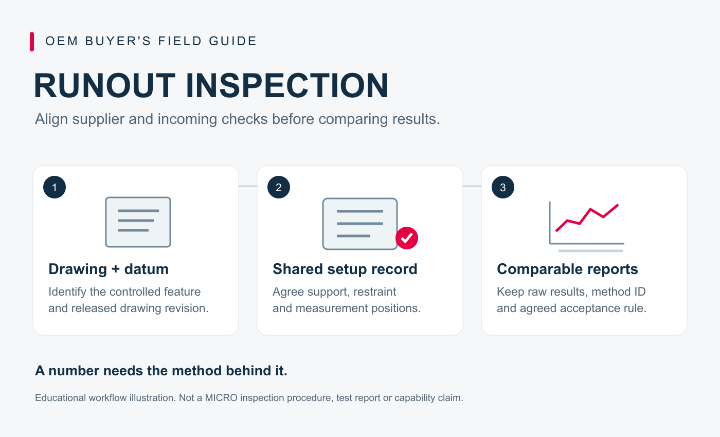
Two teams can measure the same shaft and report different runout results without having established that they evaluated the same requirement. Before ordering precision shafts, agree how the drawing will become a shared inspection procedure. A number headed “runout” leaves too much of that procedure invisible.
The shaft drawing guide explains the geometric requirements. Here, the focus is the supplier-to-receiving handover.
Start with the characteristic, then choose the setup
Identify the released drawing revision, geometric control, controlled surface, datum references and measurement direction. Record the invoked standard and edition. ASME's Y14.5 overview explains its role in defining and interpreting GD&T. The released drawing governs acceptance.
For a radial journal check, establish what surface must rotate about which datum axis. A different rotational axis changes the question being asked. Do not let “held in a chuck” or “checked between centres” replace the drawing's datum interpretation without technical review.
KEYENCE distinguishes circular from total runout: circular runout concerns a section during rotation, while total runout addresses the specified surface together. A report of indicator variation at one section does not establish total runout across a journal.
Make a setup record both teams can reproduce
Ask the supplier and receiving team to review one setup sketch or photograph with labelled references. Identify the actual datum-contact surfaces, supports, axial location and retention arrangement. State how the required datum axis is established, rather than describing only the instrument.
Confirm how centres, collets or supports relate to the specified datum features. A manufacturing centre hole or convenient diameter should not silently replace the drawing's acceptance datum.
Describe contact and restraint conditions sufficiently for a technical review. For a slender shaft, flag questions about support, retention and probe contact before choosing a measurement procedure. This guide specifies no universal clamping force, support spacing or instrument: suitability depends on the actual part and required measurement.
| Setup-record field | What to identify before approval |
|---|---|
| Requirement | Drawing revision, characteristic ID, control and datum references |
| Datum establishment | Contacted features and how the specified axis is realized |
| Support and restraint | Fixture identity, contact locations and retention procedure |
| Measurement path | Probe direction, named positions or evaluated surface coverage |
| Part condition | Finished operations, cleanliness and any specified conditioning |
| Result definition | Units, evaluated quantity, reporting format and decision rule |
Mahr's commutator-shaft example describes recording precise support-prism positions in work instructions. That illustrates setup documentation; its equipment and operating ranges are not a recommendation for every shaft or a claim about MICRO's equipment.
Give measurement locations names that survive handover
Avoid instructions such as “near the end.” Mark each selected position on an approved inspection sketch, referenced to identifiable drawing geometry. Identify the viewing direction on a stepped shaft.
Distinguish the controlled length from the positions used to evaluate it. Identify transitions, reliefs, grooves and other boundaries. For circular runout, agree the required section coverage; for total runout, agree how the specified surface will be evaluated. A list of selected sections is not automatically sufficient for a total-runout control.
Mitutoyo's measurement guide illustrates radial and axial runout relative to a datum axis and distinguishes line-based from surface-based evaluation. Keep a shoulder's axial check separate from a journal's radial check when both are specified. The same report heading should not conceal different sensing directions.
Also identify the manufacturing stage represented by the result. If treatment or finishing follows an intermediate check, say which requirements must be verified again on the delivered component. The heat-treatment and grinding guide addresses that stage-to-stage connection.
Example: resolve two reports before deciding conformity
The identifiers below describe a hypothetical teaching record. They are not a MICRO part, customer case, inspection result or qualified method. No tolerance or measured value is proposed.
Drawing EDU-R01 Rev B identifies a radial runout requirement on journal J2 relative to datum feature A. Supplier report SR-01 and incoming report IR-01 both contain a row labelled “runout.” Their support records reveal different information:
| Review question | Supplier record SR-01 | Incoming record IR-01 | Required resolution |
|---|---|---|---|
| Which physical part? | Identified sample S-01 | Batch identity only | Identify the inspected part before comparing results |
| Which rotational reference? | Setup record names datum feature A | “Between centres” only | Review how each setup establishes the required datum axis |
| Which measurement position? | Approved position P1 on J2 | “Near shoulder” | Map both checks to defined drawing locations |
| Which surface condition? | After final finishing | Stage not recorded | Confirm that both results concern the same delivered condition |
These records do not yet support a direct comparison. Close the missing information and agree remeasurement on identified parts.
Keep both original reports and the revised setup record. Record what changed, who approved it and which characteristics require review. If the methods still disagree after alignment, escalate the measurement investigation rather than changing the drawing limit or averaging incompatible results.
Request evidence that supports the acceptance decision
Specify whether the report must include actual results, characteristic and sample identities, setup revision, evaluated positions and applicable acceptance limits. An “OK” entry cannot provide actual readings requested for sample approval.
Ask how the complete measurement method is shown to be suitable for the requirement. NIST explains that traceability alone does not establish fitness for purpose: an instrument's calibration does not, by itself, establish the suitability of every result obtained with it.
Agree how measurement uncertainty and the conformity decision will be handled, especially when a result is close to a limit. Avoid substituting the instrument display resolution for a review of the complete method. No universal resolution ratio or guard band is specified here.
Keep sample approval and production sampling distinct. Define how many parts and which characteristics are evaluated at each stage, and how changes to fixtures, programs or inspection coverage are reviewed. Use the sample approval guide to connect those decisions to the released records.
Include the inspection plan in the enquiry
For motor shafts or stepped shafts, send the drawing and highlight the journals or shoulders requiring runout evidence. Include the intended datum interpretation, proposed inspection sketch, finished condition, report needs and unresolved receiving-method questions.
Discuss the arrangement through MICRO's quality page, then include it with the RFQ checklist. The quotation should confirm the agreed inspection scope for the actual geometry; this guide does not guarantee a runout value or a particular fixture.
Start an enquiry and email the drawing and inspection requirements to [email protected] with the enquiry reference. Agree the measurement handover before production.