
Give each locator a defined job
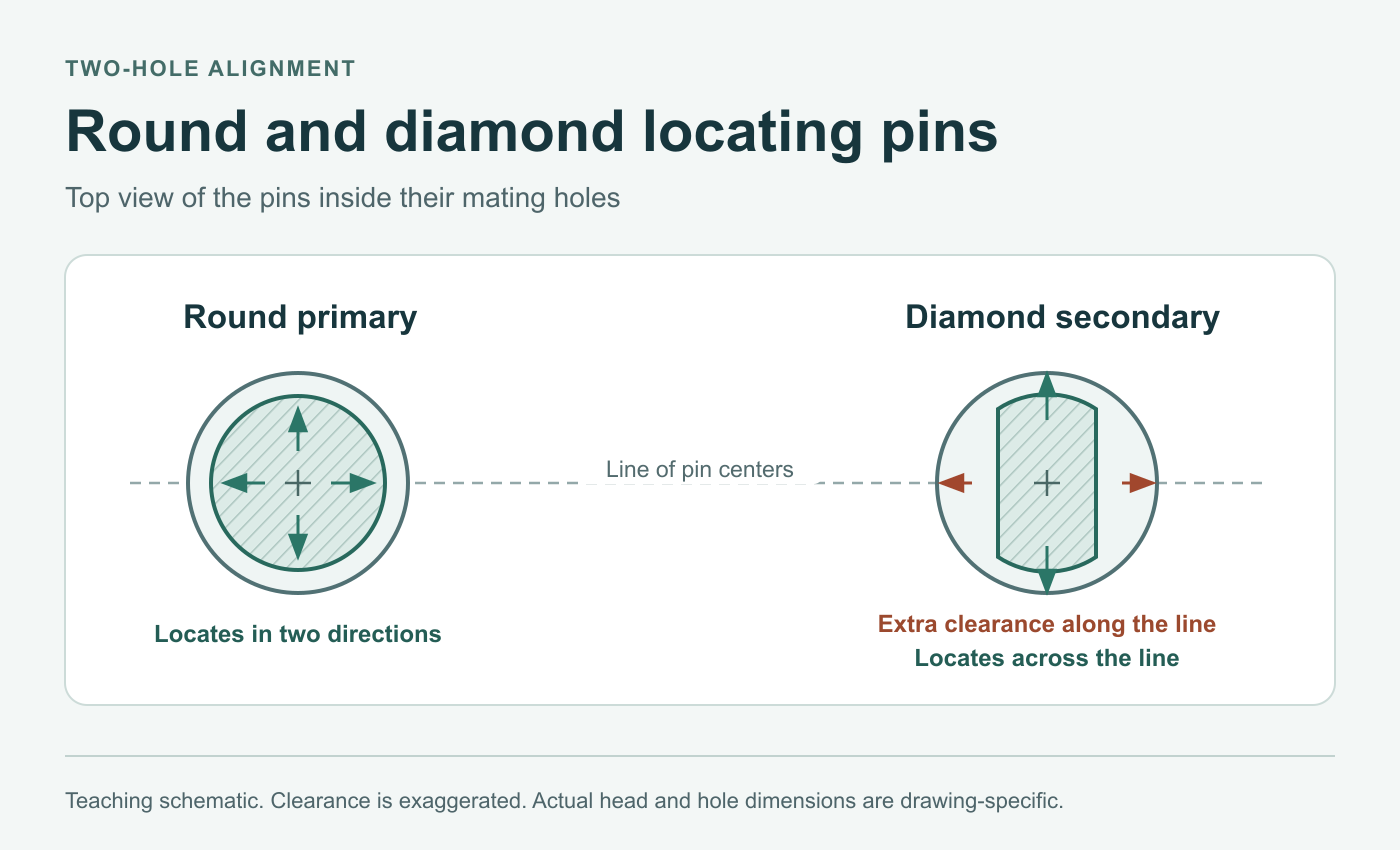
Picture a plate lowered onto a fixture base. The support face establishes how the plate seats vertically. The round pin locates the first hole in two in-plane directions, within its fit clearance. The plate can still turn around that pin. A diamond pin in the second round hole limits this rotation. Its head is relieved along the line between the pin centers, so small differences in hole spacing can be accommodated in that direction. The fit across the remaining lands still determines part of the play in the installed orientation. Carr Lane's round and diamond pin guidance
On the assembly drawing, label the primary round locator and show the line through its center and the secondary pin center. In an end view looking down the insertion axes, mark the smaller width parallel to that line and the locating width perpendicular to it. This view gives the installer a direction to check after mounting the pin. An arrow pointing to the word “diamond” leaves the contact direction open. A quarter-turn error can consume the intended pitch clearance and leave angular play in the direction that was meant to locate. MISUMI locating pin paper, figure 2
Check the pattern alongside the local fits
Each hole can meet its diameter tolerance and still bind when both pins enter together. Two close-fitting round heads both try to locate their hole centers in both directions. If the actual distance between the hole centers differs from the installed pin spacing, that mismatch consumes available clearance. A diamond head makes room for some of that mismatch along the centerline. Side-to-side error, pin tilt, burrs and misaligned mounting bores can still interfere.
Review the allowable combinations of finished hole sizes and positions, installed pin positions and head geometry. Include any coating on the fitting surfaces. Check clearance along the centerline and the allowable angular movement after the plate seats. A tighter fit across the lands may reduce angular movement and make loading less forgiving. The head profile and the receiving hole together set the usable clearance, so assess combined offsets instead of assuming the full relief width is available in every position. For single-interface size and finished-condition terms, see the mating-fit guide.
Define the head and mounting shank separately
Specify the finished round head diameter and usable engagement length. On the diamond head, show the locating width across the lands, relieved profile or width, engagement length and allowed orientation relative to the mounting reference. If the shank stays in the fixture, its retention and replacement method belong to a different interface from the removable plate's fit over the head. State which face sets the installed height, and check that the plate seats on its intended supports before a pin shoulder interferes or a pin tip bottoms in a blind hole.
If operators load parts often, review the entry lead-in, insertion direction and access for replacement. A taller primary pin can begin locating first where the available height allows it. Agree the straight locating length separately. Provide a way to check or restore the secondary pin's orientation after service. MISUMI positioning tutorial, figures 3–6
Where the design permits a changed receiver, a slotted locator bushing is another way to put directional clearance at the second hole. Evaluate its mounting orientation and service method as part of the assembly. Jergens slotted locator bushing example
Send these details with the RFQ
| Item | What to put in the quote package |
|---|---|
| Location scheme | Assembly section, support and locating faces, primary hole, secondary hole and insertion direction |
| Hole and pin pattern | Finished hole size and position limits, installed pin pattern limits and the required angular location |
| Finished heads | Round head diameter, diamond locating width and relieved profile, lead-in and usable engagement |
| Mounting and service | Shank size and retention, installed height, orientation reference and replacement access |
| Inspection scope | Drawing revisions, measurement conditions and results required for heads, holes and installed pattern |
| Assembly trial | Identified hardware, loading procedure, seating and angular criteria, repeated-loading scope and owner |
Agree two kinds of acceptance evidence
The component report can show pin head size, relieved profile and orientation reference. It should identify which features were measured and the condition of the parts. Hole size checks and pattern or installed-pin checks each need a defined method, because an individual plug check cannot measure the relationship between the two holes. The gauge selection guide explains how to match evidence to a size requirement.
If the order requires repeated loading, record the actual plate and locator set, its mounted orientation, and the loading, seating and angular criteria under the agreed conditions. Agree how many cycles and what combination of parts to try. A trial on one identified pair demonstrates that pair under those conditions. Interchangeability across lots needs evidence selected for that scope.
In a hypothetical assembly check, a plate with two in-tolerance hole diameters takes each round pin separately but stops before seating over both together. The review finds that the hole pattern and installed pin pattern are at opposite permitted ends of their spacing limits. The design owner approves a relieved secondary profile, checks the allowable spacing and angular movement, and updates the assembly drawing. The follow-up records the exact trial parts, full seating and the measured angular location. When you request a quote for precision pins, include the mating drawing and intended checks. The quality page describes the documentation available for project review.