
A pin that passes its own diameter check can still be difficult to assemble. A sleeve that meets its outside dimensions may still be the wrong match for the shaft or housing. When ordering custom pins and bushings, define the interfaces as well as the individual component.
The questions below help a buyer prepare the assembly information for supplier review. They are a specification checklist, not a table of recommended fits. The responsible design engineer must define the required fit and acceptance limits for the actual mechanism.
Start with what the part must do
Does the pin locate two components, act as a removable pivot, or remain fixed in one member? Does the metal sleeve guide another part, provide a locating shoulder, or simply maintain a distance? Record the intended function before choosing which dimensions need particular control.
Use a short assembly sketch to identify the moving and stationary members. Mark the surfaces that touch and explain which component is installed first. If one end of a pin must remain fixed while the other permits movement, identify those interfaces separately. A note saying “tight fit” does not explain that distinction.
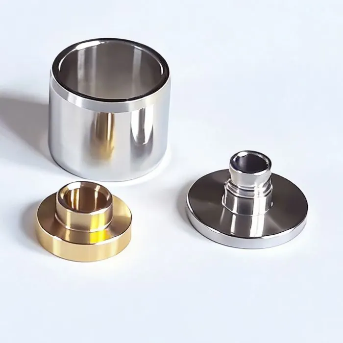
Photographs of custom precision pins and metal bushings and spacers show possible component forms. Specific form examples include pins with circumferential grooves and flanged bushings. These photographs do not determine the fit, load capacity or material of your assembly.
Specify the pin and hole together
Give the pin diameter limits and the corresponding mating-hole limits, including which drawing governs each part. Add the hole depth, whether it is through or blind, and any shoulder or stop that determines the final pin position.
SPIROL's straight and dowel solid-pin guidance describes a press-fit example in which the hole is smaller than the pin. It stresses controlled interference and the influence of the host material. This illustrates why a pin drawing alone is insufficient; it does not supply a universal fit for every custom pin.
State the housing or mating-part material and the intended installation method. If disassembly is required, describe how the pin will be removed and which parts must be reusable. Keep assembly requirements separate from a supplier's loose-part inspection obligations unless both have been explicitly agreed.
For bushings, map the inside and outside interfaces
A metal bushing can have two relevant mating surfaces: its outside diameter against a housing, and its bore against a shaft or pin. The requirement at one interface does not define the other. Identify both mating components and provide their drawing references where necessary.
For a flanged form, also define the flange diameter, thickness and seating face. Explain which face sets the axial position and whether the bore must be evaluated in the supplied condition or after installation. If your design needs installed-condition acceptance, describe the host component and the agreed verification arrangement before ordering.
Do not infer a bearing duty from the word “bushing.” A turned sleeve used as a spacer has different questions to resolve from a component intended for relative motion. Supply the operating context for review rather than selecting a fit from an unrelated catalogue.
Make the interface checklist explicit
Use one row for each actual contact or locating feature. The entries below are questions to complete, not prescribed tolerances.
| Component feature | Mating feature | Information to provide |
|---|---|---|
| Pin diameter | Hole in the host part | Both size limits, host material and intended retention or movement |
| Pin end or shoulder | Stop face or hole bottom | Installed depth, assembly direction and axial-position requirement |
| Bushing outside diameter | Housing bore | Both drawing references, fit requirement and installation method |
| Bushing bore | Shaft or pin | Required clearance or other fit condition, controlled length and inspection condition |
| Flange seating face | Housing face | Axial location, face requirements and any assembly restriction |
| Entry edges | Mating-part entry | Defined edge condition, installation direction and burr acceptance |
Ask your engineering team to identify any interface still under review. Label it as open in the RFQ and record the assumption used for the quotation. Close it before releasing the order; a supplier's commercial offer should not silently become the assembly design.
Define edges, assembly direction and finished condition
Edge preparation deserves a drawing note when it affects assembly. SPIROL's hole-preparation white paper discusses how burrs and entry conditions affect pin installation, with recommendations depending on the pin and host material. Its examples should not be copied as a universal chamfer requirement for metal sleeves or other pin designs.
Instead, state the required entry feature and permitted burr condition on the relevant drawing. Identify whether the part enters from one direction or either end. When a treatment or coating is specified, clarify which dimensions apply to the finished part and whether any area must remain untreated.
Appearance alone cannot establish the material or coating. Specify the material designation, condition and required treatment in the enquiry, even if the supplied photograph looks similar to a previous component.
Agree on part acceptance and assembly acceptance
Separate two questions: what must the supplier measure on the delivered component, and what will your team verify in the assembly? List the critical features, required inspection records and any agreed trial-assembly step. State who supplies the mating components and who approves the result.
Where an interface also involves a rotating shaft, include the relevant shaft drawing requirements. The guide to diameter, straightness and runout explains why these controls answer different questions. Avoid replacing a missing datum or geometric requirement with a general request for greater accuracy.
Before requesting a quotation, check that the part revision, mating-part references, quantities and unresolved questions are consistent. The CNC turned parts RFQ checklist provides a reusable commercial and technical cover sheet. To discuss a MICRO component, send an enquiry and email the drawings to [email protected]. Include the interface information that affects your part so it can be reviewed with the drawing.