
Applications · made to your drawing
Motor shafts made to your assembly drawing
Define bearing seats, rotor interfaces and inspection references before reviewing a custom motor shaft for manufacture.
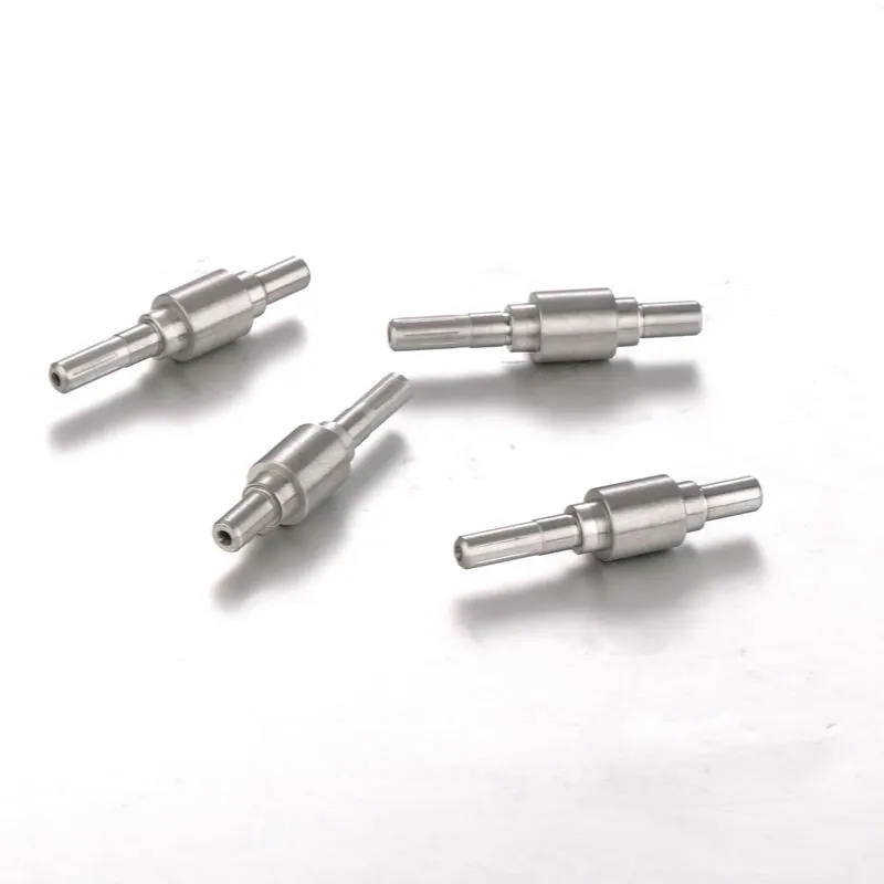
The important dimensions on a motor shaft depend on what each section does in the assembly. A bearing seat, rotor interface and output end can have different fit, surface and geometric requirements. MICRO makes motor shafts to customer drawings, with the key diameters and surfaces controlled to the agreed specification. This page helps prepare a useful enquiry for that manufacturing review. It does not replace motor design validation or establish a speed, load, vibration or noise rating for the finished motor.
Identify the function of each shaft section
Mark the shaft sections that locate bearings, support the rotor or connect to the driven component. Explain the purpose of shoulders, grooves, flats and other features that affect position or assembly. For a fit requirement, supply its drawing limits rather than asking for a generally tight shaft. This makes it easier to review the relevant surfaces without applying the same requirements to every diameter.
- Show the bearing-seat locations and their specified size and surface requirements.
- Identify the rotor or other mating interface and the finished-condition dimensions.
- Define the output-end geometry and any edges needing particular attention during assembly.
Review the route and sample evidence together
Manufacturing may combine turning, grinding and other operations required by the drawing. Material, feature geometry and any treatment influence the route, so we review feasibility for the actual part. Include the sample quantity, expected production quantities and inspection records needed for approval. If motor-level performance depends on the shaft, describe the relevant component requirements; a conforming shaft inspection alone does not validate the complete motor assembly.
Plan the next step
Connect your application, part geometry and required evidence before placing an order.
Related technical guides
Explore manufacturing · Inspection equipment and certificates
Questions before you enquire
Can you choose the bearing fit for our motor?
MICRO works to customer designs. Supply the required fit or dimensional limits and the mating information available; engineering reviews manufacturability rather than taking responsibility for the motor design.
Does a shaft runout result predict motor vibration?
A shaft measurement verifies the defined component characteristic under its inspection conditions. Motor vibration depends on the assembled system and requires the buyer's relevant assembly and performance validation.
What is needed to review a motor-shaft enquiry?
Send the drawing revision, material and treatment requirements, key mating surfaces, geometric inspection requirements and quantities. Include any special sample or production documentation needs.