
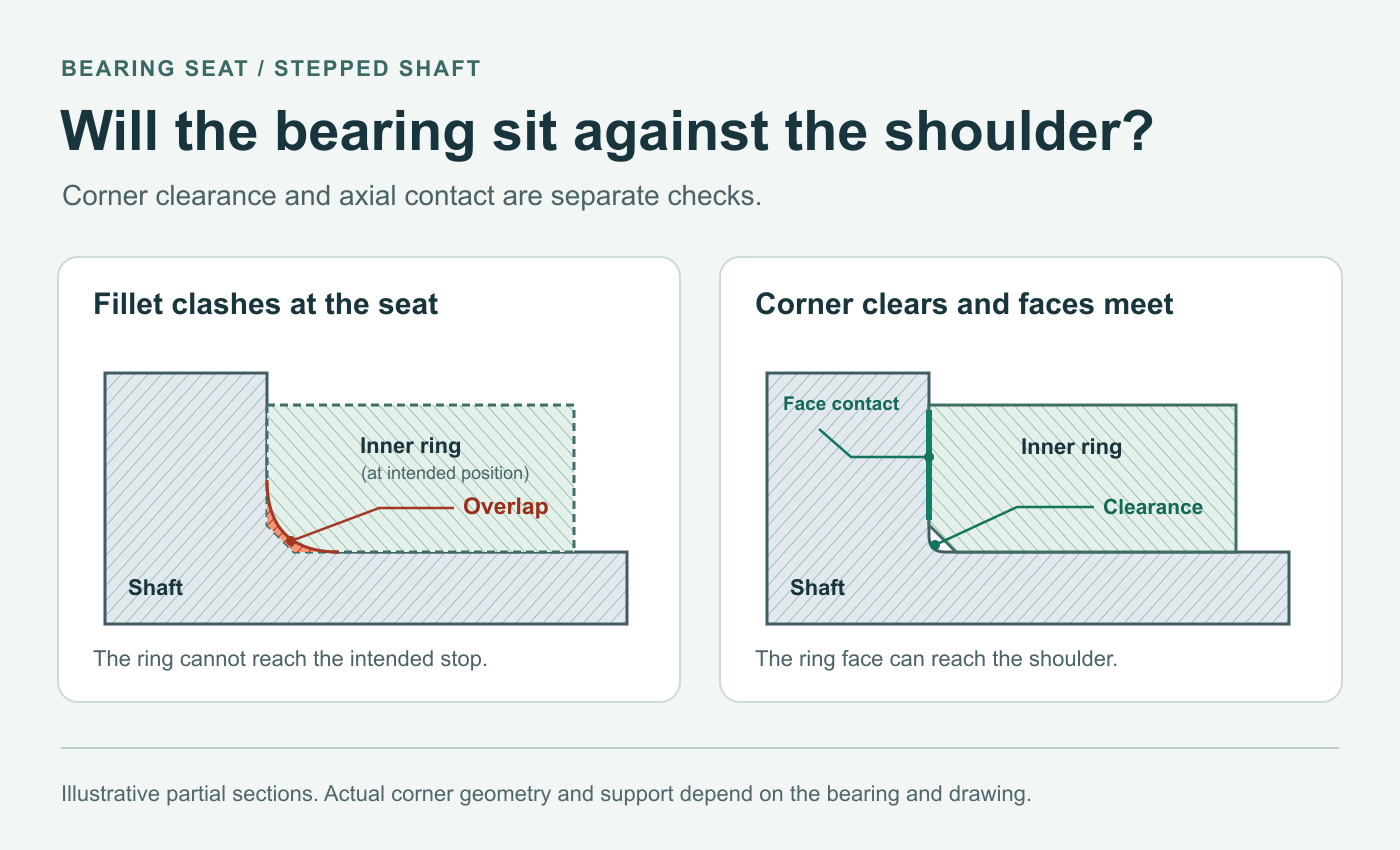
A bearing can fit the shaft diameter and still stop before its inner ring reaches the shoulder. At the corner, the shaft fillet may project into the space needed by the ring chamfer. On stepped shafts, identify the intended ring, stop face and corner together on the assembly section before finalizing the shaft drawing.
Read the bearing drawing and the shaft drawing together
On the shaft, the cylindrical seat locates the bore and the shoulder face provides the intended axial stop in a direct-abutment design. The fillet is the rounded transition between them. The bearing has an edge break at the bore-to-face corner. Set the shaft profile so that the bearing’s flat end face can reach the shoulder without the two corner profiles conflicting. A chamfer at the entry end of the shaft helps the bearing start onto the seat and is a separate feature from the shoulder transition. NSK guidance on shafts and housings
Ask for the complete bearing designation and the manufacturer’s installation drawing or table. Use the allowable mating fillet and abutment dimensions for the ring face that goes against the shoulder. Catalogues may show a minimum bearing chamfer dimension and a maximum shaft fillet in separate fields. Match the label to the drawing and check the most restrictive combination of permitted profiles. A nominal chamfer dimension alone leaves the clearance unresolved. Review approved substitutes against the same interface, even if their bore, outside diameter and width match.
Preserve the flat area that supports the ring
Once the corners clear, check the annular area where the shoulder can support the flat ring face. A shoulder with too little usable face can leave the ring poorly supported. A larger shoulder can also enter space needed by adjacent components. Use the bearing maker’s applicable abutment dimensions, then check the assembly for axial loads, clearance and any access needed for removal. Put the drawing-defined face location and geometric control in the inspection plan. NTN Rolling Bearings Handbook, section 15.2
If the shaft needs a larger blend for strength, ask the design owner to review the arrangement. An engineered spacer with clearance on the shaft side may accommodate the blend, provided the assembly has an adequate support area and the spacer thickness is included in the axial stack. Resolve how the spacer contacts both surfaces and which way it is fitted. A relieved spacer becomes a controlled assembly component.
Define a relief if the approved design calls for one
A relief is a recessed corner profile. It can provide tool or wheel runout and may also create room for the bearing corner. Specify its required width, depth, location and blend, or reference the exact approved standard form and size. Include the resulting usable seat length and shoulder contact area in the design review. A relief removes material at the transition, so have engineering review the remaining section and load path before changing the print. ISO 18388 relief groove types and dimensioning
Ask the shaft supplier to review this geometry in the intended process. An accessible turned corner and a corner that must clear a grinding wheel may need different tooling or a different approved profile. Agree the required shape and edge condition after the final operation. For a ground or coated seat, identify which finished surfaces the measurements describe. Sandvik Coromant external turning and corner relief guidance
Put the interface details in the quotation package
| Item | What the buyer should give or confirm |
|---|---|
| Bearing and orientation | Complete bearing designation, maker’s installation data, selected ring face and approved alternates |
| Released drawing | Shaft and assembly revisions, a section through the corner and the intended axial stop |
| Seat and shoulder | Required finished seat size and length, usable shoulder face and the axial reference for inspection |
| Transition | Permitted fillet or controlled relief profile, finished condition and adjacent edge requirements |
| Spacer, if specified | Detail drawing, orientation, support faces and place in the axial stack |
| Acceptance evidence | Agreed profile method, accessible finished measurement locations and any required assembly sample |
Ask the supplier to identify drawing questions and inspection scope in the quote. A profile trace or optical check can be useful when access and resolution are appropriate for the part. If a sectioned sample is needed, agree how it will be prepared and identified. Agree which reported dimensions correspond to the corner and the shoulder face. See the inspection-report checklist for tying a result to its drawing requirement and sample.
Verify seating from an agreed reference
Agree whether the order needs finished shaft measurements, an assembly trial, or both. If a trial is required, identify the bearing, shaft sample, installation direction and manufacturer-approved mounting method. Record the installed position of an accessible reference face relative to a named shaft reference. A visible gap check may supplement that result where there is access and an agreed criterion. Document which surfaces were checked and the installation condition.
Consider a fictional motor assembly with two sample shafts that both pass the journal diameter check. The ring on one sample stops short in the agreed installation setup. The buyer confirms the bearing designation and orientation and asks the supplier to check the seat for fit, debris or burrs, then compare the actual corner profile and shoulder location with the drawing. Measured corner profiles overlap at the intended seated position on the affected sample. Engineering approves a revised profile and checks that the remaining flat shoulder provides the intended support. The retest records the released revision, the profile result and the ring position from the same shaft reference.
For precision shafts, include the bearing data and any required seating check when you request a quote. The quality page explains the supporting documentation available for project review.